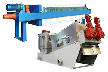
Hydraulic Filter Press


The filter presses usually used for drying sludge are easily mechanized plate types for discharging sludge cake. Selecting a hydraulic system and controls for the filter press allows for automation without human intervention. The type of hydraulic system usually depends on the size of the filter press required. Three common types of hydraulic systems for filter presses include pneumatic, electric and manual.
Filter press controls are a factor in the type of hydraulic system to be used as well as other details such as automatic valves, drip pans, automatic plate changers, and/or options for automatic high-pressure cloth washing units. Various manifold processes can also be facilitated more easily by using appropriate controls such as uniform fill, pre-coat, acid wash, core blow, cake wash, etc.
How does a hydraulic filter press work?
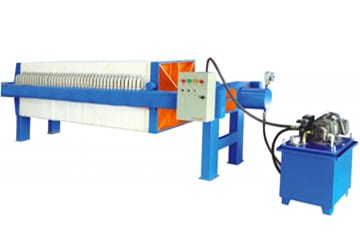
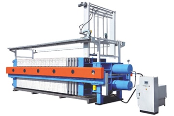
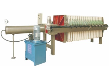
Pneumatic hydraulics and control
For added operator and equipment protection, the hydraulics are enclosed within the legs of the filter press that support the hydraulic cylinders. 100 psi air is used to pressurize the reservoir used to push the plate stack closed. Once the plate stack is closed, the high pressure pneumatic hydraulic pump clamps the plate stack with a force, plus a safety factor, to counteract the pressure of the slurry feed.
The pneumatic-hydraulic pump unit converts plant air into hydraulic pressure through a simple ratio system that uses a large air piston area at low pressure to produce high hydraulic pressure on a small hydraulic piston area. The automatic reciprocating motion is controlled by the action of a pilot-operated selector valve in the pneumatic section of the pump.
As the hydraulic output approaches the desired pressure indicated by the pneumatic regulator setting, the pump decelerates and eventually stops when the hydraulic pressure balances the air pressure. The hydraulic pressure is maintained and no power is consumed.
When the cycle is complete, the air-hydraulic system releases the pressure in the cylinder and uses air pressure to retract the follower and discharge the filter cake. The air-hydraulic control switch and gauges are mounted on the left or right side of the filter press legs to accommodate the installation.
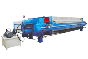
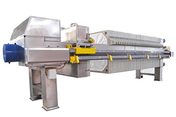
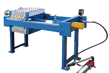
Electrohydraulics and control
The electro-hydraulic pumping unit holds the hydraulic pressure and if the pressure exceeds the release setting, that pressure is vented – keeping the pressure within the specified range.
For added operator and equipment protection, the hydraulic power unit is enclosed within the legs of the filter press and is used to support the hydraulic cylinders. It consists of a high volume/low pressure pump for rapid opening and closing of the plate stack and a low volume/high pressure pump for clamping the plate stack. Once the plate stack is closed, the high pressure hydraulic pump clamps the plate stack with a force, plus a safety factor, to counteract the pressure of the slurry feed.
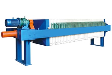
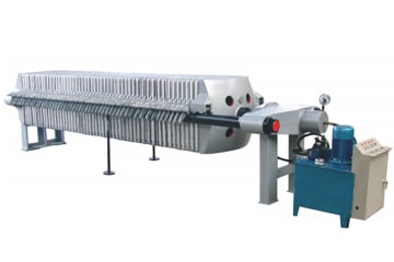
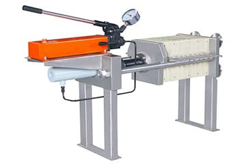
Manual hydraulics and controls
The hydraulic cylinder swings from the “up” to the “clamping” position and the manual pump works to build up clamping pressure. At the end of the dewatering cycle, the hydraulic pressure is released and the cylinder is retracted by an internal spring. The cylinder is then lifted to the “up” position and the follower is manually pulled back to the end of the press. The filter plate is then manually moved to discharge the filter cake.Advantages
Popular articles
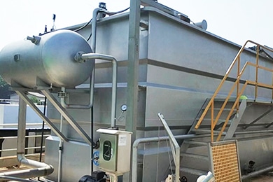
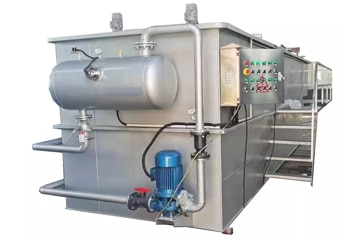
Dissolved Air Flotation
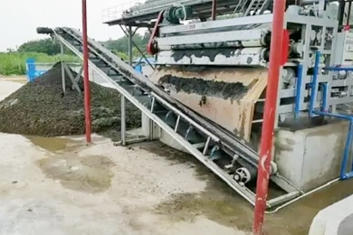
Solid Liquid Separation
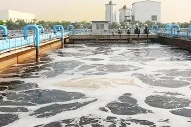
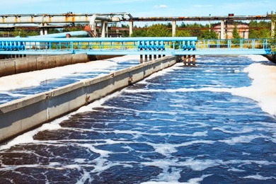
What is Activated Sludge?
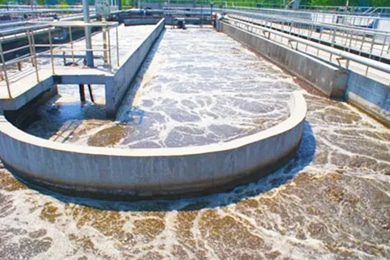
Sewage Sludge Overview
Industrial Waste Water
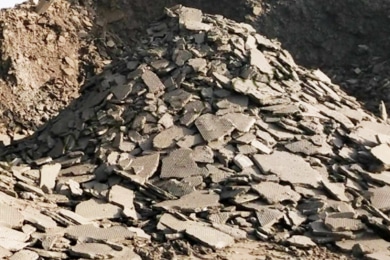
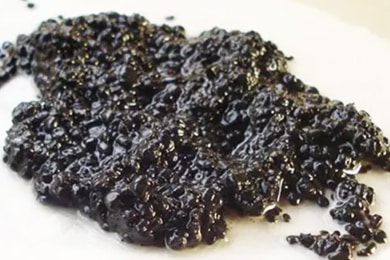
What is Sludge Cake?
What is Industrial Sludge?